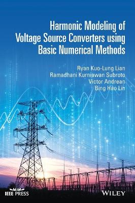
Harmonic Modeling of Voltage Source Converters using Basic Numerical Methods
 -15%
portes grátis
Harmonic Modeling of Voltage Source Converters using Basic Numerical Methods
Andrean, Victor; Subroto, Ramadhani Kurniawan; Lin, Bing Hao; Lian, Ryan Kuo-Lung
John Wiley & Sons Inc
12/2021
416
Dura
Inglês
9781119527138
15 a 20 dias
938
Acknowledgments xvii
List of Symbols xix
1 Fundamental Theory 1
1.1 Background 1
1.2 Definition of Harmonics 2
1.3 Fourier Series 2
1.3.1 Trigonometric Form 3
1.3.2 Phasor Form 4
1.3.3 Exponential Form 4
1.4 Waveform Symmetry 5
1.4.1 Even Symmetry 5
1.4.2 Odd Symmetry 6
1.4.3 Half-Wave Symmetry 6
1.5 Phase Sequence of Harmonics 8
1.6 Frequency Domain and Harmonic Domain 8
1.7 Power Definitions 9
1.7.1 Average Power 9
1.7.2 Apparent and Reactive Power 9
1.8 Harmonic Indices 11
1.8.1 Total Harmonic Distortion (THD) 11
1.8.2 Total Demand Distortion (TDD) 12
1.8.3 True Power Factor 12
1.9 Detrimental Effects of Harmonics 13
1.9.1 Resonance 13
1.9.2 Misoperations of Meters and Relays 17
1.9.3 Harmonics Impact on Motors 18
1.9.4 Harmonics Impact on Transformers 18
1.10 Characteristic Harmonic and Non-Characteristic Harmonic 19
1.11 Harmonic Current Injection Method 21
1.12 Steady-State vs. Transient Response 21
1.13 Steady-State Modeling 22
1.14 Large-Signal Modeling vs. Small-Signal Modeling 24
1.15 Discussion of IEEE Standard (STD) 519 25
1.16 Supraharmonics 30
2 Power Electronics Basics 37
2.1 Some Basics 37
2.2 Semiconductors vs. Wide Bandgap Semiconductors 38
2.3 Types of Static Switches 40
2.3.1 Uncontrolled Static Switch 40
2.3.2 Semi-Controllable Switches 41
2.3.3 Controlled Switch 42
2.4 Combination of Switches 44
2.5 Classification Based on Commutation Process 45
2.6 Voltage Source Converter vs. Current Source Converter 46
3 Basic Numerical Iterative Methods 49
3.1 Definition of Error 49
3.2 The Gauss-Seidel Method 50
3.3 Predictor-Corrector 52
3.4 Newton's Method 55
3.4.1 Root Finding 55
3.4.2 Numerical Integration 56
3.4.3 Power Flow 57
3.4.4 Harmonic Power Flow 61
3.4.5 Shooting Method 63
3.4.6 Advantages of Newton's Method 67
3.4.7 Quasi-Newton Method 69
3.4.8 Limitation of Newton's Method 71
3.5 PSO 71
4 Matrix Exponential 73
4.1 Definition of Matrix Exponential 74
4.2 Evaluation of Matrix Exponential 75
4.2.1 Inverse Laplace Transform 75
4.2.2 Cayley-Hamilton Method 76
4.2.3 Pade Approximation 78
4.2.4 Scaling and Squaring 80
4.3 Krylov Subspace Method 80
4.4 Krylov Space Method with Restarting 83
4.5 Application of Augmented Matrix on DC-DC Converters 86
4.6 Runge-Kutta Methods 90
5 Modeling of Voltage Source Converters 95
5.1 Single-Phase Two-Level VSCs 95
5.1.1 Switching Functions 95
5.1.2 Switched Circuits 97
5.2 Three-Phase Two-Level VSCs 99
5.3 Three-Phase Multilevel Voltage Source Converter 112
5.3.1 Multilevel PWM 112
5.3.2 Diode Clamped Multilevel VSCs 114
5.3.3 Flying Capacitor Multilevel VSCs 120
5.3.4 Cascaded Multi-Level VSCs 128
5.3.5 Modular Multi-Level VSC 140
6 Frequency Coupling Matrices 149
6.1 Construction of FCM in the Harmonic Domain 149
6.2 Construction of FCM in the Time Domain 155
7 General Control Approaches of a VSC 179
7.1 Reference Frame 179
7.1.1 Stationary-abc Frame 179
7.1.2 Stationary-???? Frame 180
7.1.3 Synchronous-dq Frame 181
7.1.4 Phase-Locked Loop 182
7.2 Control Strategies 183
7.2.1 Vector-Current Controller 183
7.2.2 Direct Power Controller 186
7.2.3 DC-bus Voltage Controller 188
7.2.4 Circulating Current Controller 189
8 Generalized Steady-State Solution Procedure for Closed-Loop Converter Systems 193
8.1 Introduction 193
8.2 Generalized Procedure 193
8.2.1 Step 1: Determine How and Where to Break the Loop 195
8.2.2 Step 2: Check if the Calculation Flows of the Broken System are Feasible 195
8.2.3 Step 3: Determine What Domain of Each Component in the System Should be Modeled 196
8.2.4 Step 4: Formulate the Mismatch Equations 197
8.2.5 Step 5: Iterate to Find the Solution 197
8.3 Previously Proposed Methods Derived from the Proposed Solution Procedures 197
8.3.1 Steady-State Methods Derived from Loop-Breaking 1 Method 197
8.3.2 Steady-State Methods Derived from Loop-Breaking 2 Method 198
8.4 The Loop-Breaking 3 Method 200
9 Loop-Breaking 1 Method 205
9.1 A Typical Two-Level VSC with AC Current Control and DC Voltage Control 205
9.2 Loop-Breaking 1 Method for a Two-Level VSC 206
9.2.1 Block 1 208
9.2.2 Current Controller Block 208
9.2.3 Voltage Controller Block 210
9.3 Solution Flow Diagram 210
9.3.1 Initialization 212
9.3.2 Jacobian Matrix 212
9.3.3 Number of Modulating Voltage Harmonics to be Included 228
10 Loop-Breaking 2 Method for Solving a VSC 245
10.1 Modeling for a Closed-Loop DC-DC Converter 245
10.1.1 Model of the Buck Converter 245
10.1.2 Constraints of Steady-State 247
10.1.3 Switching Time Constraints 248
10.1.4 Solution Flow Diagram 248
10.2 Two-Level VSC Modeling: Open-Loop Equations 252
10.2.1 Steady-State Constraints 256
10.2.2 Switching Time Constraints 257
10.2.3 Solution Flow Diagram 260
10.2.4 Initialization 260
10.2.5 Jacobian Matrix 260
10.2.6 Discussions of Results 269
10.3 Comparison Between the LB 1 and LB 2 Methods 270
10.3.1 Case #1: Balanced System 270
10.3.2 Case #2: Unbalanced System with AC Waveform Exhibiting Half-Wave Symmetry 270
10.3.3 Case #3: Unbalanced System, No Waveform Symmetry 272
10.4 Large-Signal Modeling for Line-Commutated Power Converter 272
10.4.1 Discontinuous Conduction Mode 273
10.4.2 Continuous Conduction Mode 282
10.4.3 Steady-State Constraint Equations 284
10.4.4 General Comments 291
11 Loop-Breaking 3 Method 293
11.1 OpenDSS 293
11.2 Interfacing OpenDSS with MATLAB 294
11.3 Interfacing OpenDSS with Harmonic Models of VSCs 299
12 Small-Signal Harmonic Model of a VSC 315
12.1 Problem Statement 315
12.2 Gauss-Seidel LB 3 and Newton LB 3 316
12.2.1 Current Injection Method 316
12.2.2 Norton Circuit Method 317
12.3 Small-Signal Analysis of DC-DC Converter 320
12.4 Small-Signal Analysis of a Two-Level VSC 325
12.4.1 Approach from Section 12.3 325
12.4.2 Simpler Approach 326
13 Parameter Estimation for a Single VSC 335
13.1 Background on Parameter Estimation 335
13.2 Parameter Estimator Based on White-Box-and-Black-Box Models 337
13.3 Estimation Validations 339
13.3.1 Experimental Validation 340
13.3.2 PSCAD/EMTDC Validation 343
14 Parameter Estimation for Multiple VSCs with Domain Adaptation 349
14.1 Introduction of Deep Learning 349
14.2 Domain Adaptation 351
14.3 Parameter Estimation for Multiple VSCs 352
14.4 Notations for DA 353
14.5 Supervised Domain Adaptation for Regression 355
14.6 Supervised Domain Adaptation for Classification 356
14.7 Test Setup 358
14.7.1 Data Generator 359
14.7.2 Data Preprocessing 359
14.8 Performance Metrics 361
14.8.1 R square (Regression) 361
14.8.2 Mean Absolute Percentage Error, MAPE (Regression) 361
14.8.3 Accuracy (Classification) 362
14.8.4 F1 score (Classification) 362
14.9 Test Results 363
14.9.1 Classification Task on Multiple VSC 363
14.9.2 Regression Task on Multiple VSC 363
14.10 Software for Running the Codes 370
14.11 Implementation of Domain Adaptation 370
14.11.1 Data Generation 370
14.11.2 Regression 372
14.11.3 Classification network 375
References 379
Index 389

