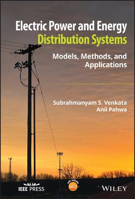
Electric Power and Energy Distribution Systems
 -15%
portes grátis
Electric Power and Energy Distribution Systems
Models, Methods, and Applications
Venkata, Subrahmanyam S.; Pahwa, Anil
John Wiley & Sons Inc
11/2022
368
Dura
Inglês
9781119838258
15 a 20 dias
666
Preface xxi
Organization of the Book xxiii
Acknowledgments xxv
About the Companion Website xxvi
1 Introduction 1
1.1 Prologue 1
1.2 The Past 1
1.3 The Present 2
1.4 The Future 2
1.5 New Developments 3
1.6 Epilogue 3
1.7 The Electric Power System 4
1.8 Distribution System Devices 5
1.8.1 Substation Devices 6
1.8.1.1 Power Transformers 6
1.8.1.2 Switchgear 7
1.8.1.3 Compensating Devices 7
1.8.1.4 Protection Equipment 8
1.8.1.5 Control and Monitoring Devices 8
1.8.2 Primary System Components 8
1.8.2.1 Feeders and Laterals 9
1.8.2.2 Switches 9
1.8.2.3 Compensating Devices 10
1.8.2.4 Protection Equipment 10
1.8.2.5 Control and Monitoring Devices 11
1.8.2.6 Distribution Transformers 11
1.8.2.7 Types of Primary Systems 11
1.8.3 Secondary System Components 11
1.9 Frequently Asked Questions on Distribution Systems 12
Reference 12
2 Distribution System Transformers 13
2.1 Definition 13
2.2 Types of Distribution Transformers 13
2.2.1 Overhead Transformers 13
2.2.2 Underground Transformers 14
2.3 Standards 14
2.3.1 Loading of Transformers 14
2.3.2 Types of Cooling 15
2.3.2.1 OA - Oil-Immersed Self-Cooled 15
2.3.2.2 OA/FA - Oil-Immersed Self-Cooled/Forced-Air Cooled 15
2.3.2.3 OA/FA/FOA - Oil-immersed Self-Cooled/Forced-Air Cooled/Forced-Oil Forced-Air Cooled 16
2.3.2.4 FOA - Oil-Immersed Forced-Oil Cooled with Forced-Air Cooled 16
2.3.2.5 OW- Oil-ImmersedWater Cooled 16
2.3.2.6 FOW- Oil-Immersed Forced-Oil Cooled with Forced-Water Cooled 17
2.3.2.7 AA - Dry-Type Self-cooled 17
2.3.2.8 AFA - Dry-Type Forced-Air Cooled 17
2.3.2.9 AA/FA - Dry-Type Self-cooled/Forced-Air Cooled 17
2.3.3 Terminal Markings and Polarity 17
2.3.4 Insulation Class 17
2.4 Single-Phase Transformer 18
2.4.1 Model for a Single-Phase Transformer 18
2.4.2 Performance Analysis 20
2.4.3 Regulation 20
2.4.4 Taps 21
2.5 Distribution Transformer Connections 21
2.5.1 Example 22
2.5.2 Parallel Operation of Three-wire Transformers 23
2.5.3 Single-Phase Autotransformers 25
2.6 Three-Phase Transformer Connections 26
2.6.1 Analysis of Y/? Transformer with Unbalanced Load 27
2.6.2 Analysis of Y/Y Transformer 29
2.6.3 Three-winding Transformer 31
Problems 33
References 34
3 Distribution Line Models 35
3.1 Overview 35
3.2 Conductor Types and Sizes 35
3.2.1 Sizes 35
3.2.2 Overhead Feeders 35
3.2.3 Underground Feeders 36
3.2.4 Conductor Data 37
3.3 Generalized Carson's Models 38
3.4 Series Impedance Models of Overhead Lines 39
3.4.1 Three-phase Line 39
3.4.2 Single- and Two-phase Line Modeling 42
3.4.3 Three-phase Line Example 42
3.5 Series Impedance Models of Underground Lines 44
3.5.1 Nonconcentric Neutral Cables 44
3.5.2 Concentric Neutral Cables 45
3.5.2.1 Single-phase Cable 45
3.5.2.2 Three-phase Cable 46
Problems 49
References 52
4 Distribution System Analysis 53
4.1 Introduction 53
4.2 Modeling of Source Impedance 53
4.3 Load Models 54
4.3.1 Load Model I 54
4.3.2 Load Model II 56
4.3.3 Load Model III 56
4.3.4 Load Model IV 57
4.4 Distributed Energy Resources (DERs) 57
4.5 Power Flow Studies 61
4.5.1 Line Model 62
4.5.2 Load and DER Model 63
4.5.3 Computing Currents 65
4.5.4 Power Flow Algorithm 66
4.6 Voltage Regulation 68
4.6.1 Voltage Regulation Definition 68
4.6.2 Approximate Method for Voltage Regulation 69
4.6.3 Voltage Drop on Radial Feeders with Uniformly Distributed Load 72
4.6.4 Voltage Drop on a Radial Feeder Serving a Triangular Area 74
4.7 Fault Calculations 75
4.7.1 Prefault System 76
4.7.2 Three-phase Fault 78
4.7.3 Double-Line-to-Ground (DLG) Fault 79
4.7.4 Single-Line-to-Ground (SLG) Fault 80
4.7.5 Line-to-Line (LL) Fault 80
4.7.6 Symmetrical Component-based Fault Analysis 81
4.7.6.1 Three-phase Fault 82
4.7.6.2 DLG Fault 83
4.7.6.3 SLG Fault 84
4.7.6.4 LL Fault 85
Problems 86
References 88
5 Distribution System Planning 89
5.1 Introduction 89
5.2 Traditional vs. Modern Approaches to Planning 90
5.3 Long-term Load Forecasting 90
5.4 Load Characteristics 92
5.4.1 Customer Classes 92
5.4.2 Loads in a Modern House 94
5.4.3 Time Aggregation 95
5.4.4 Diversity and Coincidence 96
5.4.5 Demand Factor 101
5.4.6 Load Duration Curve 101
5.4.7 Load Factor 103
5.4.8 Loss Factor 103
5.5 Design Criteria and Standards 105
5.5.1 Voltage Standards 105
5.5.2 Conservation Voltage Reduction 106
5.6 Distribution System Design 107
5.6.1 Substation Design 107
5.6.2 Design of Primary Feeders 108
5.6.3 Design of Secondary Systems 111
5.6.4 Underground Distribution Systems 111
5.6.5 Rural vs. Urban Systems 113
5.7 Cold Load Pickup (CLPU) 114
5.7.1 CLPU Fundamentals 114
5.7.2 CLPU Models 115
5.7.3 Impacts of CLPU 116
5.7.4 Operating Limits 117
5.8 Asset Management 117
Problems 118
References 121
6 Economics of Distribution Systems 123
6.1 Introduction 123
6.2 Basic Concepts 123
6.2.1 Interest Rate 123
6.2.2 Inflation 124
6.2.3 Discount Rate 124
6.2.4 Time Value of Money 124
6.2.5 Annuity 125
6.2.6 PresentWorth of Annuity 125
6.2.7 PresentWorth of Geometric Series 125
6.3 Selection of Devices: Conductors and Transformers 126
6.3.1 Distribution Feeder Conductors 126
6.3.1.1 Conductor Economics 126
6.3.1.2 Reach of Feeders 129
6.3.1.3 Optimal Selection of Conductors for Feeders 132
6.3.1.4 Example 135
6.3.2 Economic Evaluation of Transformers 136
6.4 Tariffs and Pricing 138
6.4.1 Electricity Rates 138
6.4.1.1 Energy 138
6.4.1.2 Demand 139
6.4.1.3 Time of Use (TOU) 139
6.4.1.4 Critical Peak Pricing (CPP) 139
6.4.1.5 Critical Peak Rebates (CPRs) 139
6.4.1.6 Interruptible Rates 140
6.4.1.7 Power Factor-Based Rates 140
6.4.1.8 Real-Time Price 140
6.4.1.9 Net Metering 140
6.4.2 Understanding Electricity Bills 141
6.4.2.1 Monthly Rate 141
6.4.3 Rural Electric Cooperatives (RECs) 142
6.4.4 Municipal Utilities 142
Problems 143
References 146
7 Distribution System Operation and Automation 147
7.1 Introduction 147
7.2 Distribution Automation 148
7.3 Communication Infrastructure 151
7.4 Distribution Automation Functions 151
7.4.1 Outage Management 153
7.4.2 Feeder Reconfiguration 154
7.4.3 Voltage and var Management 155
7.4.3.1 Transformer LTC Operation 155
7.4.3.2 Capacitor Operation 156
7.4.3.3 Regulator Operation 157
7.4.3.4 Smart Inverters 157
7.4.4 Monitoring and Control 159
7.4.4.1 Transformer Life Extension 159
7.4.4.2 Recloser/Circuit Breaker Monitoring and Control 160
7.5 Cost-Benefit of Distribution Automation 160
7.5.1 Higher Energy Sales 162
7.5.2 Reduced Labor for Fault Location 162
7.5.3 O&M of Switches and Controllers 162
7.5.4 Lesser Low-Voltage Complaints 162
7.6 Cost-Benefit Case Studies 163
References 165
8 Analysis of Distribution System Operation Functions 169
8.1 Introduction 169
8.2 Outage Management 169
8.2.1 Trouble Call Analysis 171
8.2.1.1 Outage Location Using Escalation Methods 172
8.2.1.2 Rule-Based Escalation 173
8.2.1.3 Test Cases 175
8.3 Voltage and var Control 178
8.3.1 Load Tap Changer 178
8.3.2 Line Regulators 179
8.3.3 Capacitors 179
8.3.4 Capacitor Placement 180
8.3.4.1 Illustrative Example 181
8.3.5 Capacitor Switching and Control 185
8.4 Distribution System Reconfiguration 185
8.4.1 Multiobjective Reconfiguration Problem 185
8.4.1.1 Minimization of Real Loss 186
8.4.1.2 Transformer Load Balancing 186
8.4.1.3 Minimization of Voltage Deviation 187
8.4.2 Illustrative Example 187
8.5 Distribution System Restoration 188
8.5.1 Step-by-Step Restoration 189
8.5.2 Restoration Times 191
8.5.3 Derivation of Restoration Times 192
8.5.4 Optimal Operation and Design for Restoration During CLPU 193
8.5.4.1 Thermally Limited System 193
8.5.4.2 Voltage Drop Limited System 194
References 195
9 Distribution System Reliability 197
9.1 Motivation 197
9.2 Basic Definitions 198
9.3 Reliability Indices 201
9.3.1 Basic Parameters 201
9.3.2 Sustained Interruption Indices 202
9.3.2.1 System Average Interruption Frequency Index (SAIFI) 202
9.3.2.2 System Average Interruption Duration Index (SAIDI) 202
9.3.2.3 Customer Average Interruption Duration Index (CAIDI) 203
9.3.2.4 Customer Total Average Interruption Duration Index (CTAIDI) 203
9.3.2.5 Customer Average Interruption Frequency Index (CAIFI) 203
9.3.2.6 Average Service Availability Index (ASAI) 203
9.3.2.7 Customers Experiencing Multiple Interruptions (CEMIn) 204
9.3.2.8 Customers Experiencing Long Interruption Durations (CELID) 204
9.3.3 Load-based Indices 204
9.3.3.1 Average System Interruption Frequency Index (ASIFI) 204
9.3.3.2 Average System Interruption Duration Index (ASIDI) 205
9.3.4 Momentary Interruption Indices 205
9.3.4.1 Momentary Average Interruption Frequency Index (MAIFI) 205
9.3.4.2 The Momentary Average Interruption Event Frequency Index (MAIFIE) 205
9.3.4.3 Customers Experiencing Multiple Sustained Interruption and Momentary Interruption Events Index (CEMSMIn) 205
9.3.5 Sustained Interruption Example 206
9.3.6 Momentary Interruption Example 208
9.4 Major Event Day Classification 209
9.5 Causes of Outages 210
9.5.1 Trees 211
9.5.2 Lightning 211
9.5.3 Wind 212
9.5.4 Icing 213
9.5.5 Animals/Birds 213
9.5.6 Vehicular Traffic 214
9.5.7 Age of Components 214
9.5.8 Conductor Size 214
9.6 Outage Recording 214
9.7 Predictive Reliability Assessment 216
9.7.1 Component Failure Models 216
9.7.2 Network Reduction 217
9.7.3 Markov Modeling 219
9.7.4 Failure Modes and Effects Analysis (FMEA) 223
9.7.4.1 FMEA Method Assumptions 223
9.7.4.2 FMEA Procedure 223
9.7.5 Monte Carlo Simulation 225
9.8 Regulation of Reliability 226
Problems 227
References 229
10 Distribution System Grounding 231
10.1 Basics of Grounding 231
10.1.1 Need for Grounding 231
10.1.2 Approaches for Grounding 231
10.1.3 Effects of Grounding on System Models 233
10.2 Neutral Grounding 233
10.2.1 Neutral Shift Due to Ground Faults 233
10.2.2 Types of Neutral Grounding 234
10.2.3 Standards for Neutral Grounding 234
10.3 Substation Safety 234
10.4 National Electric Safety Code (NESC) 236
10.5 National Electric Code (NEC) 236
References 238
11 Distribution System Protection 239
11.1 Overview and Philosophy 239
11.2 Role of Protection Studies 240
11.3 Protection of Power-carrying Devices 241
11.4 Classification of Protective and Switching Devices 241
11.4.1 Single-action Fuses 241
11.4.1.1 Expulsion Fuses 242
11.4.1.2 Vacuum Fuses 243
11.4.1.3 Current-limiting Fuses 243
11.4.1.4 Distribution Fuse Cutouts 244
11.4.2 Automatic Circuit Reclosers 244
11.4.2.1 Recloser Classifications 247
11.4.3 Sectionalizers 247
11.4.4 Circuit Breakers 249
11.4.5 Time Overcurrent Relays 250
11.4.6 Static or Solid-state Relays 254
11.4.7 Digital or Numerical Relays 254
11.4.8 Load Break Switch 255
11.4.9 Circuit Interrupter 255
11.4.10 Disconnecting Switch 255
11.4.11 Sectionalizing Switch 255
11.4.12 Example Distribution System 255
11.5 New Generation of Devices 256
11.5.1 Smart Switching Devices 256
11.5.1.1 Smart Fuses 257
11.5.1.2 Smart Reclosers (Interrupters) 257
11.5.1.3 Smart Circuit Breakers 257
11.6 Basic Rules of Classical Distribution Protection 257
11.6.1 Operational Convention for Protective Devices 258
11.6.2 Protecting Feeder Segments and Taps 258
11.7 Coordination of Protective Devices 258
11.7.1 General Coordination Rule 259
11.7.2 Fuse-Fuse Coordination 259
11.7.2.1 Model for Fuses 259
11.7.2.2 Rule for Fuse-Fuse Coordination 260
11.7.3 Recloser-Fuse Coordination 262
11.7.4 Recloser-Sectionalizer Coordination 270
11.7.4.1 Rule for Coordination 270
11.7.5 Circuit Breaker-Recloser Coordination 270
11.7.5.1 Models for Relay-controlled Circuit Breakers 270
11.7.5.2 Rule for Coordination 270
11.8 New Digital Sensing and Measuring Devices 272
11.8.1 Phasor Measurement Units (PMUs) 272
11.8.2 Microphasor Measurement Units 272
11.8.3 Optical Line Current Sensors 273
11.8.4 Optical Voltage Sensors 274
11.8.5 Digital Pressure and Temperature Sensors 274
11.8.6 Evolving Sensors 274
11.9 Emerging Protection System Design and Coordination 274
Problems 275
References 277
12 Power Quality for Distribution System 279
12.1 Definition of Power Quality 279
12.2 Impacts of Power Quality 280
12.2.1 The Customer Side 280
12.2.2 The Utility Side 281
12.2.3 Importance of Power Quality 281
12.2.4 Cost of Power Quality 281
12.3 Harmonics and PQ Indices 281
12.3.1 Total Harmonic Distortion (THD) 281
12.3.1.1 Properties of THD 282
12.3.2 Total Demand Distortion (TDD) 283
12.3.3 Power Factor (PF) 283
12.3.4 Standards for Harmonic Control 284
12.4 Momentary Interruptions 286
12.5 Voltage Sag and Swell 286
12.5.1 Definition 286
12.5.2 ITI (CBEMA) Curve 287
12.6 Flicker 289
Problems 290
References 290
13 Distributed Energy Resources and Microgrids 293
13.1 Introduction 293
13.2 DER Resources and Models 293
13.2.1 Wind Generation 293
13.2.2 Solar Generation 295
13.2.3 Battery Energy Storage System (BESS) 296
13.2.4 Microturbine 298
13.2.5 Electric Vehicles 298
13.3 Interconnection Issues 299
13.4 Variable Solar Power 299
13.5 Microgrids 303
13.5.1 Microgrid Types by Supply and Structure 303
13.5.1.1 ac Microgrids 303
13.5.1.2 dc Microgrids 304
13.5.1.3 Hybrid Microgrids 305
13.5.1.4 Networked Microgrids 305
13.5.2 Microgrid Modes of Operation 305
13.5.2.1 Grid-Connected Mode 305
13.5.2.2 Islanded Mode 306
13.5.3 Grid-Following vs. Grid-Forming Inverters 308
13.5.4 Microgrid Protection Challenges and Requirements 309
13.5.5 Examples of Microgrid in Operation 310
13.5.5.1 CERTS Microgrid 310
13.5.5.2 IIT Microgrid 311
13.5.5.3 Philadelphia Navy Yard Microgrid 312
13.6 Off-Grid Electrification 312
13.6.1 Designing Off-Grid Systems 313
13.6.1.1 Load Estimation 313
13.6.1.2 Resource Assessment 313
13.6.1.3 Optimal System Design 313
13.6.1.4 Other Factors 314
References 314
Appendix A Per-unit Representation 317
A.1 Single-phase Systems 317
A.2 Three-phase Systems 318
A.2.1 Per-unit Values for ?-Connected Systems 318
A.2.2 Per-unit Values for ?-Connected Systems 319
A.3 Base Values for Transformers 319
A.4 Change of Base 320
A.5 Advantages of Per-unit Representation 320
Appendix B Symmetrical Components 323
Index 327

