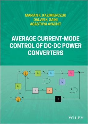
Average Current-Mode Control of DC-DC Power Converters
 -15%
portes grátis
Average Current-Mode Control of DC-DC Power Converters
Saini, Dalvir K.; Ayachit, Agasthya; Kazimierczuk, Marian K.
John Wiley & Sons Inc
03/2022
336
Dura
Inglês
9781119525653
15 a 20 dias
722
About the Authors xvii
Preface xix
Acknowledgments xxi
1 Introduction 1
1.1 Principle of Operation of Conventional Average Current-Mode Control Technique 3
1.2 Principle of Operation of Modified Average Current-Mode Control Technique 6
1.3 Steady-State Operation 7
2 Average Current-Mode Control of Buck DC-DC Converter 9
2.1 Circuit Description, DC Characteristics, and Design 10
2.1.1 Circuit Description 10
2.1.2 DC Model 10
2.1.3 Design Example 12
2.2 Large-Signal and Small-Signal Models of PWM Buck Converter in CCM 13
2.3 Power Stage Transfer Functions 15
2.3.1 Duty Cycle-to-Output Voltage Transfer Function Tp 16
2.3.2 Duty Cycle-to-Inductor Current Transfer Function Tpi 18
2.3.3 Input Voltage-to-Output Voltage Transfer Function M ?? 20
2.3.4 Input Voltage-to-Inductor Current Transfer Function M ?? i 21
2.3.5 Reverse Current Gain A i 22
2.3.6 Open-Loop Input Impedance Z i 24
2.3.7 Open-Loop Output Impedance Zo 26
2.4 Inner-Current Loop 27
2.4.1 Transfer Function of Filter and Non-inverting Amplifier Tf 29
2.4.2 Transfer Function of Pulse-Width Modulator Tm 30
2.4.3 Uncompensated Loop Gain Tki 30
2.4.4 Transfer Function of Control Circuit for Inner-Current Loop Tci 31
2.4.5 Compensated Loop Gain of Inner-Current Loop Ti 33
2.5 Closed-Loop Transfer Functions for Inner-Current Loop 34
2.5.1 Reference Voltage-to-Inductor Current Transfer Function Ticl 35
2.5.2 Reference Voltage-to-Output Voltage Transfer Function Tpicl 35
2.5.3 Input Voltage-to-Inductor Current Transfer Function Micl 36
2.5.4 Input Voltage-to-Output Voltage Transfer Function M??icl 37
2.5.5 Input Impedance Ziicl 39
2.5.6 Output Impedance Zoicl 40
2.6 Outer-Voltage Loop 42
2.6.1 Transfer Function of Feedback Network ?? 42
2.6.2 Uncompensated Loop Gain for Outer-Voltage Loop Tk?? 42
2.6.3 Transfer Function of Control Circuit for Outer-Voltage Loop Tc?? 43
2.6.4 Compensated Loop Gain of Outer-Voltage Loop T?? 46
2.7 Closed-Loop Transfer Functions for Outer-Voltage Loop 46
2.7.1 Reference Voltage-to-Output Voltage Transfer Function Tpcl 46
2.7.2 Input Voltage to Duty-Cycle Transfer Function Md?? 47
2.7.3 Input Voltage-to-Output Voltage Transfer Function M??cl 49
2.7.4 Input Impedance Zi??cl 50
2.7.5 Output Impedance Zo??cl 52
2.8 Comparison of Closed-Loop and Open-Loop Step Responses 55
2.8.1 Response of Output Voltage to Step Change in Input Voltage 55
2.8.2 Response of Output Voltage to Step Change in Duty Cycle, Current-Loop reference Voltage, and Voltage-Loop Reference Voltage 55
2.8.3 Response of Input Current to Step Change in Input Voltage 56
2.8.4 Response of Output Voltage to Step Change in Load Current 57
2.9 Summary 58
3 Average Current-Mode Control of Boost DC-DC Converter 61
3.1 Circuit Description, DC Characteristics, and Design 62
3.1.1 Circuit Description 62
3.1.2 DC Model 62
3.1.3 Design Example 65
3.2 Large-Signal and Small-Signal Models of PWM Boost Converter for CCM 66
3.3 Power-Stage Transfer Functions 67
3.3.1 Duty Cycle-to-Output Voltage Transfer Function Tp 68
3.3.2 Duty Cycle-to-Inductor Current Transfer Function Tpi 74
3.3.3 Input Voltage-to-Output Voltage Transfer Function M?? 80
3.3.4 Input Voltage-to-Inductor Current Transfer Function M??i 81
3.3.5 Reverse Current Gain Ai 82
3.3.6 Open-Loop Input Impedance Zi 84
3.3.7 Open-Loop Output Impedance Zo 85
3.4 Inner-Current Loop 88
3.4.1 Transfer Function of Filter and Non-inverting Amplifier Tf 89
3.4.2 Transfer Function of Pulse-Width Modulator Tm 90
3.4.3 Uncompensated Loop Gain Tki 90
3.4.4 Transfer Function of Control Circuit Tci 91
3.4.5 Loop Gain of Inner-Current Loop Ti 93
3.5 Closed-Loop Transfer Functions for Inner-Current Loop 94
3.5.1 Reference Voltage-to-Inductor Current Transfer Function Ticl 94
3.5.2 Reference Voltage-to-Output Voltage Transfer Function Tpicl 95
3.5.3 Input Voltage-to-Inductor Current Transfer Function Micl 96
3.5.4 Input Voltage-to-Output Voltage Transfer Function M??icl 98
3.5.5 Input Voltage-to-Duty Cycle Transfer Function Mdi 99
3.5.6 Input Impedance Ziicl 100
3.5.7 Output Impedance Zoicl 102
3.6 Outer-Voltage Loop 103
3.6.1 Transfer Function of Feedback Network ?? 104
3.6.2 Uncompensated Loop Gain for Outer-Voltage Loop Tk?? 105
3.6.3 Transfer Function of Control Circuit for Outer-Voltage Loop Tc?? 105
3.6.4 Compensated Loop Gain of Outer-Voltage Loop T?? 107
3.7 Closed-Loop Transfer Functions for Outer-Voltage Loop 107
3.7.1 Reference Voltage-to-Output Voltage Transfer Function Tpcl 108
3.7.2 Input Voltage-to-Duty Cycle Transfer Function Md?? 109
3.7.3 Input Voltage-to-Output Voltage Transfer Function M??cl 110
3.7.4 Input Impedance Zi??cl 112
3.7.5 Output Impedance Zo??cl 114
3.8 Comparison of Closed-Loop and Open-Loop Step Responses 116
3.8.1 Response of Output Voltage to Step Change in Input Voltage 116
3.8.2 Response of Output Voltage to Step Change in Duty Cycle, Current-Loop Reference Voltage, and Voltage-Loop Reference Voltage 117
3.8.3 Response of Input Current to Step Change in Input Voltage 118
3.8.4 Response of Output Voltage to Step Change in Load Current 119
3.9 Summary 120
4 Average Current-Mode Control of Buck-Boost DC-DC Converter 121
4.1 Circuit Description, DC Model, and Design 122
4.1.1 Circuit Description 122
4.1.2 DC Model 122
4.1.3 Design Example 125
4.2 Large-Signal and Small-Signal Models of PWM Buck-Boost Converter in CCM 125
4.3 Power-Stage Transfer Functions 128
4.3.1 Duty Cycle-to-Output Voltage Transfer Function Tp 129
4.3.2 Duty Cycle-to-Inductor Current Transfer Function Tpi 134
4.3.3 Input Voltage-to-Output Voltage Transfer Function M?? 139
4.3.4 Input Voltage-to-Inductor Current Transfer Function M??i 142
4.3.5 Reverse Current Gain Ai 143
4.3.6 Open-Loop Input Impedance Zi 145
4.3.7 Open-Loop Output Impedance Zo 147
4.4 Inner-Current Loop 150
4.4.1 Transfer Function of Filter Tf 152
4.4.2 Transfer Function of Pulse-Width Modulator Tm 153
4.4.3 Uncompensated Loop Gain Tki 154
4.4.4 Transfer Function of Compensation Circuit Tci 155
4.4.5 Compensated Loop Gain Ti 156
4.5 Closed-Inner Loop Transfer Functions 158
4.5.1 Reference Voltage-to-Inductor Current Transfer Function Ticl 160
4.5.2 Reference Voltage-to-Output Voltage Transfer Function Tpicl 161
4.5.3 Input Voltage-to-Inductor Current Transfer Function Micl 162
4.5.4 Input Voltage-to-Output Voltage Transfer Function M??icl 163
4.5.5 Input Voltage-to-Duty Cycle Transfer Function Mdi 166
4.5.6 Input Impedance Ziicl 166
4.5.7 Output Impedance Zoicl 168
4.6 Outer-Voltage Loop 170
4.6.1 Transfer Function of Feedback Network ?? 172
4.6.2 Uncompensated Loop Gain Tk?? 173
4.6.3 Transfer Function of Control Circuit for Outer-Voltage Loop Tc?? 174
4.6.4 Compensated Loop Gain T?? 176
4.7 Closed-Loop Transfer Functions for Outer-Voltage Loop 176
4.7.1 Reference Voltage-to-Output Voltage Transfer Function Tpcl 177
4.7.2 Input Voltage-to-Duty Cycle Transfer Function Md?? 177
4.7.3 Input Voltage-to-Output Voltage Transfer Function M??cl 179
4.7.4 Input Impedance Zi??cl 181
4.7.5 Output Impedance Zo??cl 183
4.8 Comparison of Closed-Loop and Open-Loop Step Responses 186
4.8.1 Response of Output Voltage to Step Change in Input Voltage 186
4.8.2 Response of Output Voltage to Step Change in Duty Cycle, Current-Loop reference Voltage, and Voltage-Loop Reference Voltage 187
4.8.3 Response of Input Current to Step Change in Input Voltage 188
4.8.4 Response of Output Voltage to Step Change in Load Current 188
4.9 Summary 189
5 Average Current-Mode Control of Flyback DC-DC Converter 191
5.1 Circuit Description, DC Model, and Design 192
5.1.1 Circuit Description 192
5.1.2 DC Model 193
5.1.3 Derivation of Equivalent Averaged Resistance 197
5.1.4 Design Example 200
5.2 Large-Signal and Small-Signal Models of PWM Flyback Converter in CCM 200
5.3 Power-Stage Transfer Functions 204
5.3.1 Duty Cycle-to-Output Voltage Transfer Function Tp 206
5.3.2 Duty Cycle-to-Inductor Current Transfer Function Tpi 214
5.3.3 Input Voltage-to-Output Voltage Transfer Function M?? 220
5.3.4 Input Voltage-to-Inductor Current Transfer Function M??i 221
5.3.5 Reverse Current Gain Ai 223
5.3.6 Open-Loop Input Impedance Zi 226
5.3.7 Open-Loop Output Impedance Zo 228
5.4 Inner-Current Loop 229
5.4.1 Transfer Function of Filter and Non-inverting Amplifier Tf 231
5.4.2 Transfer Function of Pulse-Width Modulator Tm 233
5.4.3 Uncompensated Loop Gain Tki 233
5.4.4 Transfer Function of Compensation Circuit Tci 234
5.4.5 Compensated Loop Gain Ti 236
5.5 Closed-Loop Transfer Functions for Inner-Current Loop 238
5.5.1 Reference Voltage-to-Inductor Current Transfer Function Ticl 239
5.5.2 Reference Voltage-to-Output Voltage Transfer Function Tpicl 240
5.5.3 Input Voltage-to-Inductor Current Transfer Function Micl 241
5.5.4 Input Voltage-to-Output Voltage Transfer Function M??icl 243
5.5.5 Input Voltage-to-Duty Cycle Transfer Function Mdi 244
5.5.6 Input Impedance Ziicl 245
5.5.7 Output Impedance Zoicl 246
5.6 Outer-Voltage Loop 248
5.6.1 Transfer Function of Feedback Network ?? 250
5.6.2 Uncompensated Loop Gain Tk?? 250
5.6.3 Transfer Function of Compensation Circuit Tc?? 251
5.6.4 Compensated Loop Gain T?? 253
5.7 Closed-Loop Transfer Functions for Outer-Voltage Loop 253
5.7.1 Reference Voltage-to-Output Voltage Transfer Function Tpcl 254
5.7.2 Input Voltage-to-Duty Cycle Transfer Function Md?? 254
5.7.3 Input Voltage-to-Output Voltage Transfer Function M??cl 257
5.7.4 Input Impedance Zi??cl 259
5.7.5 Output Impedance Zo??cl 261
5.8 Comparison of Closed-Loop and Open-Loop Step Responses 262
5.8.1 Response of Output Voltage to Step Change in Input Voltage 262
5.8.2 Response of Output Voltage to Step Change in Duty Cycle, Current-Loop Reference Voltage, and Voltage-Loop Reference Voltage 264
5.8.3 Response of Input Current to Step Change in Input Voltage 265
5.8.4 Response of Output Voltage to Step Change in Load Current 266
5.9 Summary 266
References 269
Appendix A Design Equations for Continuous-Conduction Mode 275
A.1 Common Equations Needed for the Design of Converters 275
A.1.1 DC Output Power 275
A.1.2 DC Voltage Transfer Function 275
A.2 Specific Expressions for the Design of Converters in CCM 275
Appendix B MOSFET Parameters 277
Appendix C Diode Parameters 279
Appendix D Selected MOSFETs' Spice Models 281
D.1 IRF430 281
D.2 IRF520 281
D.3 IRF150 281
D.4 IRF142 281
D.5 IRF840 282
D.6 IRF740 282
Appendix E Selected Diodes' Spice Models 283
E.1 MUR1560 283
E.2 MBR10100 283
E.3 MBR1060 283
E.4 MUR2510 283
E.5 MBR2540 283
E.6 MBR4040 284
Appendix F Simulation Tools 285
F.1 SPICE Model of Power MOSFETs 285
F.1.1 SPICE NMOS Syntax 286
F.1.2 SPICE NMOS Model Syntax 286
F.1.3 SPICE PMOS Model Syntax 287
F.1.4 SPICE Subcircuit Model Syntax 287
F.2 Introduction to SPICE 288
F.2.1 Passive Components: Resistors, Capacitors, and Inductors 288
F.2.2 Transformer 288
F.2.3 Temperature 288
F.2.4 Independent DC Sources 288
F.2.5 DC Sweep Analysis 289
F.2.6 Independent Pulse Source for Transient Analysis 289
F.2.7 Transient Analysis 289
F.2.8 Independent AC Sources for Frequency Response 289
F.2.9 Independent Sinusoidal AC Sources for Transient Analysis 289
F.2.10 AC Frequency Analysis 290
F.2.11 Operating Point 290
F.2.12 Starting the SPICE Program 290
F.2.13 Example Program: Diode I-V Characteristics 290
F.3 Introduction to MATLAB (R) 290
F.3.1 Getting Started 291
F.3.2 Generating an x-Axis Data 291
F.3.3 Semi-logarithmic Scale 291
F.3.4 Log-Log Scale 291
F.3.5 Generate an y-Axis Data 292
F.3.6 Multiplication and Division 292
F.3.7 Symbols and Units 292
F.3.8 x-Axis and y-Axis Labels 292
F.3.9 x-Axis and y-Axis Limits 292
F.3.10 Greek Symbols 292
F.3.11 Plot Commands 293
F.3.12 3D Plot Commands 293
F.3.13 Bode Plots 293
F.3.14 Step Response 293
F.3.15 To Save Figure 293
F.3.16 Example Program 294
F.3.17 Polynomial Curve Fitting 294
F.3.18 Bessel Functions 294
F.3.19 Modified Bessel Functions 294
F.3.20 Example MATLAB Code 294
F.4 Introduction to SABER Circuit Simulator 301
F.4.1 Setting Up a Circuit on SABER 301
F.4.2 Performing TRANSIENT Analysis on the Designed Circuit 302
F.4.3 Plotting 303
F.4.4 Printing 303
Index 305

